

chts/water temp sensor Q


Thread Starter
Registered User
Joined: May 2009
Posts: 11
From: Tempe, AZ
chts/water temp sensor Q
I have a 81 na 5spd 280zx. Long story short, I do not have a chts or a water temp sensor... my car runs like doo doo. I believe the car originally had the water temp sensor but I cannot find the wires. There is only the connector for the ttv in that area(unless that is actually the temp sensor connector and I am missing the ttv connector). I am trying to hunt down the wires to tie a new connector in, would it be possible for someone to post a pic of where the wires trace back to? I have been searching for pics/instructions for a while and cant come up with much.
Thanks!
Thanks!

Registered User
Joined: Dec 2011
Posts: 55
From: Toronto Ontario Canada
I have a 81 na 5spd 280zx. Long story short, I do not have a chts or a water temp sensor... my car runs like doo doo. I believe the car originally had the water temp sensor but I cannot find the wires. There is only the connector for the ttv in that area(unless that is actually the temp sensor connector and I am missing the ttv connector). I am trying to hunt down the wires to tie a new connector in, would it be possible for someone to post a pic of where the wires trace back to? I have been searching for pics/instructions for a while and cant come up with much.
Thanks!
Thanks!
Registered User
Joined: Dec 2011
Posts: 55
From: Toronto Ontario Canada
Registered User
Joined: Dec 2011
Posts: 55
From: Toronto Ontario Canada
my bad the connectors on the non turbos are bullet type and the harness is different one wire goes to pin 14 on the ecu harness and the other goes to the afm and pin 22 on the ecu harness you should take a look at service manual for the schematics.
Thread Starter
Registered User
Joined: May 2009
Posts: 11
From: Tempe, AZ
Ok thank you that is a start. I guess perhaps I am misstating my question. Maybe I can phrase it differently. What I am specifically looking for is the location that the wire from your chts merges into the rest of the wiring harness. I have seen the overall wiring diagram but I do not know exactly where the wires run. I appreciate your help.
Registered User
Joined: Dec 2011
Posts: 55
From: Toronto Ontario Canada
Ok thank you that is a start. I guess perhaps I am misstating my question. Maybe I can phrase it differently. What I am specifically looking for is the location that the wire from your chts merges into the rest of the wiring harness. I have seen the overall wiring diagram but I do not know exactly where the wires run. I appreciate your help.
 but im pretty sure its somewhere near the battery tray.

Grumpy & Helpful
Joined: Sep 2006
Posts: 1,415
From: Mill Creek WA
it is two wires. the connector is the same as the fuel injectors. The n/a machines had the same connector NOT bullets. download the fsm from xenon. take the pdf file to kinkos or some such and have them blow up the schematic to 11x17. makes it fairly readable. you should be able to dope it out from there.
Thread Starter
Registered User
Joined: May 2009
Posts: 11
From: Tempe, AZ
I was unable to find a decent diagram for the efi harness but did make progress. I concluded that the connector I do have does indeed belong to the the ttv based on the color of the wires(YB and GW). I traced the efi harness as well as I could but could not find any loose ends and nothing heading to the other side of the engine bay where the chts would be. I will try again tomorrow when I have more light.

The Good Twin
Joined: Aug 2005
Posts: 20,639
From: Wild Wild West, UTAH!

I concluded that the connector I do have does indeed belong to the the ttv based on the color of the wires(YB and GW). I traced the efi harness as well as I could but could not find any loose ends and nothing heading to the other side of the engine bay where the chts would be. I will try again tomorrow when I have more light.


Thread Starter
Registered User
Joined: May 2009
Posts: 11
From: Tempe, AZ
Nismo: I will be looking over that site tonight/tomorrow.
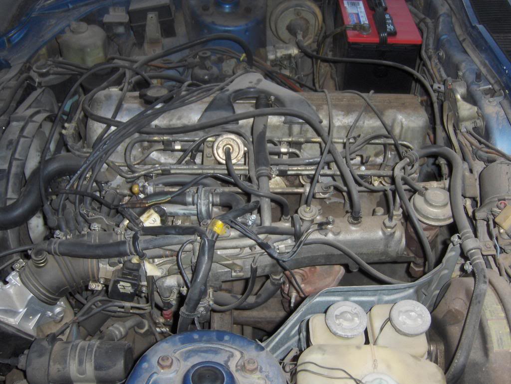
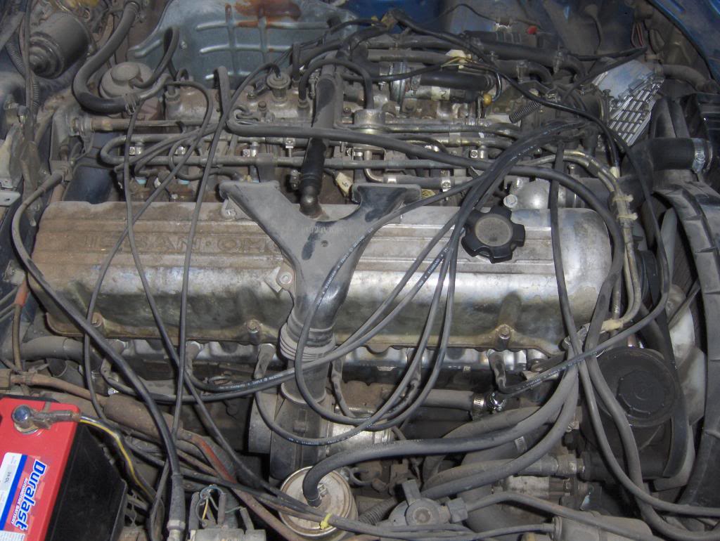
GTR: yes there is a hole on the block
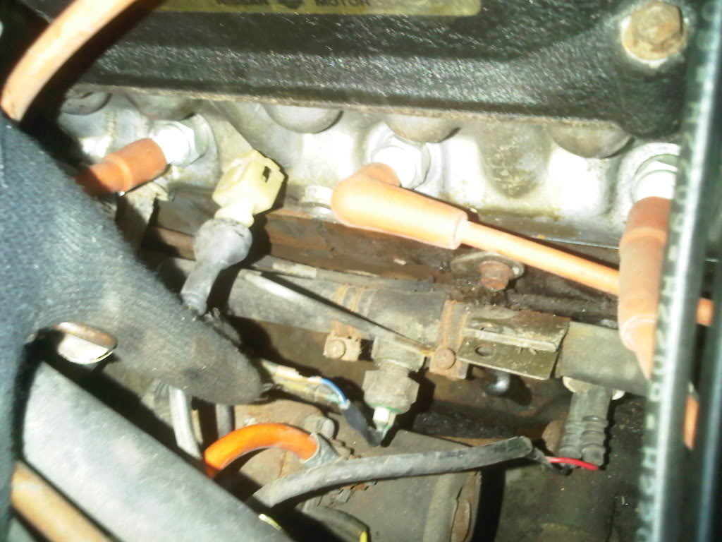
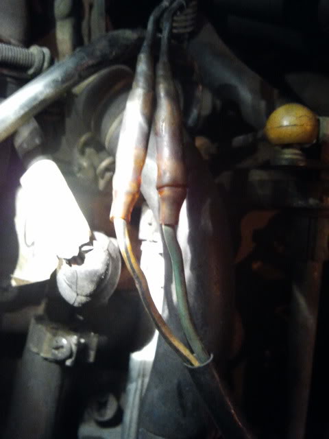
The connection that I did find, YB and GW= TTV
TTV on housing, yes I know the connector is broken
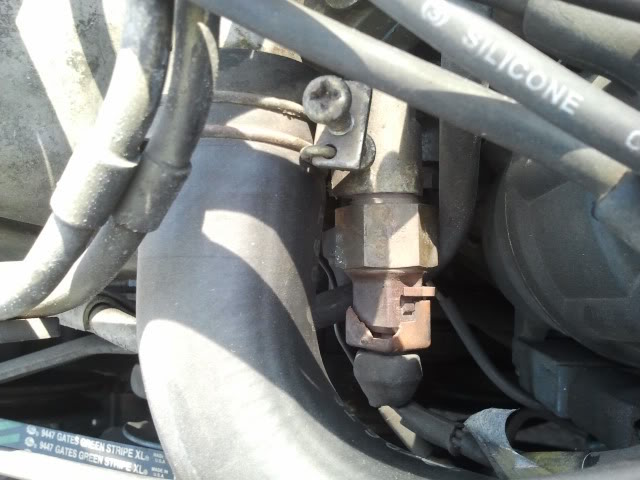
The other sensors on the thermostat housing(sorry its upside down, I could not get it to flip over)
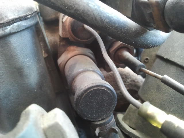
The hole where the chts goes
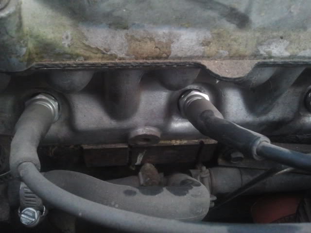
Sorry if the cell phone pics are poor quality/bad lighting. I can take more tomorrow with my camera.
The thermostat housing is not the original one. The original upper thermostat housing broke and the whole housing was replaced because it was cheaper than just the upper. The original lower was unfortunately lost. I do know that the thermal vacuum valve/ported vacuum switch is the incorrect one. It should be a white one with only 2 nipples. So yes, my thermostat housing is a mess, but its all I have to deal with...
GTR: yes there is a hole on the block
The connection that I did find, YB and GW= TTV
TTV on housing, yes I know the connector is broken
The other sensors on the thermostat housing(sorry its upside down, I could not get it to flip over)
The hole where the chts goes
Sorry if the cell phone pics are poor quality/bad lighting. I can take more tomorrow with my camera.
The thermostat housing is not the original one. The original upper thermostat housing broke and the whole housing was replaced because it was cheaper than just the upper. The original lower was unfortunately lost. I do know that the thermal vacuum valve/ported vacuum switch is the incorrect one. It should be a white one with only 2 nipples. So yes, my thermostat housing is a mess, but its all I have to deal with...
Thread Starter
Registered User
Joined: May 2009
Posts: 11
From: Tempe, AZ
Sorry, I was really busy yesterday and unable to add more photos. Please let me know if there are any other pictures that would be helpful.
My plan is to first find the connectors to install a chts because that is the most obvious fix. I will be able to further diagnose any other issues once that is fixed. Am I at least heading in the right direction?
My plan is to first find the connectors to install a chts because that is the most obvious fix. I will be able to further diagnose any other issues once that is fixed. Am I at least heading in the right direction?

Mr Z++ Wiki
Joined: Sep 2009
Posts: 2,195
From: Victoria, BC

You NEED the CHTS for the car to run properly - it's one of the major sensors for the stock ECU.
Thread Starter
Registered User
Joined: May 2009
Posts: 11
From: Tempe, AZ
Update: I found the connector!!! It was hiding twisted back behind something in the area of the battery. Thanks for the help locating it!
Ah, but now the plot thickens... I installed the sensor and hooked it up, now it wont start. I unhooked it and tried again and it sputtered but would not start. It had been starting and would eventually hold idle after a bit of coaxing the throttle. Now it barely coughs. Thinking the battery might be weak, i jumped it from another car with no improvements. Thoughts?
Ah, but now the plot thickens... I installed the sensor and hooked it up, now it wont start. I unhooked it and tried again and it sputtered but would not start. It had been starting and would eventually hold idle after a bit of coaxing the throttle. Now it barely coughs. Thinking the battery might be weak, i jumped it from another car with no improvements. Thoughts?
Registered User
Joined: Dec 2011
Posts: 55
From: Toronto Ontario Canada
Update: I found the connector!!! It was hiding twisted back behind something in the area of the battery. Thanks for the help locating it!
Ah, but now the plot thickens... I installed the sensor and hooked it up, now it wont start. I unhooked it and tried again and it sputtered but would not start. It had been starting and would eventually hold idle after a bit of coaxing the throttle. Now it barely coughs. Thinking the battery might be weak, i jumped it from another car with no improvements. Thoughts?
Ah, but now the plot thickens... I installed the sensor and hooked it up, now it wont start. I unhooked it and tried again and it sputtered but would not start. It had been starting and would eventually hold idle after a bit of coaxing the throttle. Now it barely coughs. Thinking the battery might be weak, i jumped it from another car with no improvements. Thoughts?
The Good Twin
Joined: Aug 2005
Posts: 20,639
From: Wild Wild West, UTAH!
Ah, but now the plot thickens... I installed the sensor and hooked it up, now it wont start. I unhooked it and tried again and it sputtered but would not start. It had been starting and would eventually hold idle after a bit of coaxing the throttle. Now it barely coughs. Thinking the battery might be weak, i jumped it from another car with no improvements. Thoughts?
Sounds like someone eff'd over the car and tried to make it run without the CHTS.
The Good Twin
Joined: Aug 2005
Posts: 20,639
From: Wild Wild West, UTAH!
Mr Z++ Wiki
Joined: Sep 2009
Posts: 2,195
From: Victoria, BC


Thread
Thread Starter
Forum
Replies
Last Post
Bookmarks


