
"Bumpsteer" spacers


Registered User
Joined: Mar 2002
Posts: 646
Steve,
Randy's site isn't up anymore . Remember they threatened to sue him for using
the dinosaur and the name GTZilla ? He also ran in to some bad luck and was going
through some issues . I need to grab his phone number and give him a call this weekend , and see what is going on .
Cary,
You are coming up with some way cool stuff here I am trying to follow the what all of you are saying and the funny thing its all becoming clearer on what is working for all of you. One nice thing is my car is sitting and I have done nothing to it over
the past year , so no waisted time or money yet
Mike
Randy's site isn't up anymore . Remember they threatened to sue him for using
the dinosaur and the name GTZilla ? He also ran in to some bad luck and was going
through some issues . I need to grab his phone number and give him a call this weekend , and see what is going on .
Cary,
You are coming up with some way cool stuff here
I am trying to follow the what all of you are saying and the funny thing its all becoming clearer on what is working for all of you. One nice thing is my car is sitting and I have done nothing to it overthe past year , so no waisted time or money yet
Mike

Registered User
Joined: Mar 2003
Posts: 116
From: Rickreall, OR
Originally Posted by zlalomz
Hi Mike, is Randy's website still up? I lost the URL and Cary, thanks for letting me off easy. But then if it is so simple to change the outboard pivot points in the rear how come no one has done it? I would love to see some ideas on how to do it so I don't have to chop up the unibody to raise the inner pivots. Are we talking about cutting off the arms in the picture below and adding tubular extensions? I will let you try that first since you already know my engineering skills. ") From what I understand you want the rear roll center higher than the front and it seems we are doing the opposite with a low car and front spacers. Is it not worth chasing a rear spacer idea?
From what I understand you want the rear roll center higher than the front and it seems we are doing the opposite with a low car and front spacers. Is it not worth chasing a rear spacer idea?
From what I understand you want the rear roll center higher than the front and it seems we are doing the opposite with a low car and front spacers. Is it not worth chasing a rear spacer idea?The idea that I was thinking about was to mill the arms in your pic down a bit so they were flat (on the bottom) and then put a box section on it that held heims on the outside in double shear. I'd use spacers under the box section to allow for spacing needed to change roll centers (take a look at a 956 porsche front suspension's steering arm for a pic of what the piece would look like -- I can't seem to find a pic no my PC). Connected to this box would be tubular arms similar to what I have for my EMOD car (I think you've seen a pic of those). If you make custom tubular arms then you can make a custom inner pickup at the front of the diff that should give you a few inches to play with and the back is easy.
Since the SCCA has decided to mess with the MOD rules again I'm thinking I may spend the majority of this year playing with the unibody car. So as I move more of the MOD car's suspension over I can show you pics of this in real life.
I'm also on a mission to try and convert as much of the car's alignment to shims as possible. I know this sounds silly but I actually make adjustments to my car between runs at an autox and I need a faster way of doing it.
Cary "we do this for fun, right?"
Registered User
Joined: Mar 2003
Posts: 116
From: Rickreall, OR
Originally Posted by zlalomz
I like the milling idea. Here is a pic from a 962. Something like that with the control arm heim joints in double shear?
I found a couple of pics of from the back of a JGTC Z. Turn it upside down.
Last edited by tube80z; Feb 26, 2005 at 01:00 PM.
Registered User
Joined: May 2002
Posts: 165
From: Sacramento, Ca.
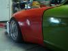
Over the weekend I tried two BS spacer combos. Two 3/4 inch spacers stacked (the black ones) and a one inch combined with a 3/4 inch. I had to remove the zerk fitting and file down a sharp edge from the bottom of the ball joint to clear the 1 and 3/4 inch combo. I am not sure how much room is left in the second one for actual bumpsteer correction with heim joints at the rod ends. I will just have to try. The last pic is where the ride heigth is with 1 and 3/4 spacer and 1 inch inner pivot raise(haven't done it yet) and the LCA level. The wheel is a 16 with 5 inch backspace. And yes Cary, that is the driver side strut on the passenger side. Oops! 
Last edited by zlalomz; Mar 1, 2005 at 09:59 AM.
Registered User
Joined: Mar 2003
Posts: 116
From: Rickreall, OR
The car looks really good. From the pic it looks like you have it set to just clear the ground on the wheels?
For bumpsteer you can move the inner rack point as well as the outer. Ideally you should be able to shim the rack as needed, which probably means a different mounting than stock. You might consider a shorter steering arm to get you quicker steering and more room. Generally the outer arm needs to go down. I have some pics of one of my old steering arms made out of flat plate that I used instead of the stock arms. I just need to find it.
I'm still trying to figure out how a 2.5 inch spacer is going to fit on John's car.
BTW, take a look at http://www.susprog.com/tutorial/tuto...tutorial02.htm. It has good info on how on what needs to be moved when you plot out what you have.
Cary
Last edited by tube80z; Mar 1, 2005 at 12:00 PM.
Registered User
Joined: May 2002
Posts: 165
From: Sacramento, Ca.
With the biggest 1 3/4 inch spacer the wheel is level to the bottom seam. So with a tire of 23.8 diameter it would be 3.9 inch clearance without the tire "squish". I am guessing 3 1/2" ride heigth.

Thread Starter
Registered User
Joined: Aug 2002
Posts: 113
From: Texas
A 2.5" spacer is not going to fit on my car. I stuck some measuring tapes under there this weekend and took some pics, and it looks like a 2.25" _might_ fit, but the steering arm will probably hit the wheel first. Heating and bending the steering arm could help to make it clear.
I am cleaning the place up before I continue, figuring I will be more motivated if I don't have to lie in metal shavings from the drill press and other stuff to get under the car. Plus I can't find any tools or move around in there because everything is strewn about the garage, and stuff left over from last summers projects are still in the way!
A bonus was I found the new pilot roller bearing I lost last fall for the new motor build!
Last edited by jburge01; Mar 1, 2005 at 02:39 PM.
Registered User
Joined: Mar 2002
Posts: 646
Now that I am totally lost on this one . Let me ask a few questions here 
When the car is lowered , the outer part of the control arm would move
up . What angle is prefered ? I take it that the angle of the steering arms plays a key role in all of this as well. Severe changes will bind the steering tie rods, since the
rack has a fixed point and the changes to the control arms would effect this. it has been mentioned that you can redrill the cross member hole 1" up for inner control arm mounting . With this and lets say a 1" spacer is the net gain about the same as
a 2" bump steer spacer . Is the steering rack design in effect during all changes of suspension angles ? I was thinking that it was with that desing steering and strut assembly .
The RC and CG are what is going to take me a bit to figure out The hard thing is the RC being below ground . What does this actually fill like ?
Mike
More questions to come
When the car is lowered , the outer part of the control arm would move
up . What angle is prefered ? I take it that the angle of the steering arms plays a key role in all of this as well. Severe changes will bind the steering tie rods, since the
rack has a fixed point and the changes to the control arms would effect this. it has been mentioned that you can redrill the cross member hole 1" up for inner control arm mounting . With this and lets say a 1" spacer is the net gain about the same as
a 2" bump steer spacer . Is the steering rack design in effect during all changes of suspension angles ? I was thinking that it was with that desing steering and strut assembly .
The RC and CG are what is going to take me a bit to figure out
The hard thing is the RC being below ground . What does this actually fill like ? Mike
More questions to come
Thread Starter
Registered User
Joined: Aug 2002
Posts: 113
From: Texas
"I take it that the angle of the steering arms plays a key role in all of this as well."
Severe changes here. No binding on the tie rods/steering arms. Of course toe changes when the car is lowered, but that is adjustable to suit your taste. Ballpark, the bottom of my control arm is 2.5" off the ground on the inside and 4.75" off the ground on the outside. No steering interference that I can tell, except I do think the top of sway bar may be touching the bottom of the frame rail in full bump.
Raising the inside or lowering the outside should have the same effect, I don't see why moving the hole up 1" would be any different than moving the ball joint down 1 inch.
Whats the RC being below ground feel like? It feels normal to me. I've been driving the car for 3 years like that. I hope there is a change in the way it feels when I move the RC up. Like maybe I am feeling that I am getting closer to catching Tom!
Registered User
Joined: Mar 2003
Posts: 116
From: Rickreall, OR
The advantage of moving the outside with a spacer is that if you set bumpsteer you shouldn't be changing the relationship -- just where you are on the curve. While moving the inside pivot would have a similar effect for the RC it will change the relationship of the steering, which will introduce bumpsteer.
For a stock length set of control arms flat or slightly drooping down (towards the outside) would be best. What you want to avoid like the plague is a RC than passes through the ground when you have significant lateral load. It feels like someone kicked the and end of the car. Very unsettling.
My EMOD car will have a front RC below ground. I chose this because it helps to slow the loading of the tire contact patch and has lower jacking forces. I can get away with this because I have extremely long arms and I don't have to worry about lateral track changes due to suspension movement. This is almost the opposite of the argument many people have for wanting a steep angle on the arms to give them camber gain. The lateral displacement causes more issues than any potential camber gain does, hence my claim of not worrying about this.
If you rasie the RC it should make that end of the car react quicker. You may also see a rise in tire temps and will most likely need to change other settings to achieve balance again.
Should I mention there are three roll centers :-)
Cary
Thread Starter
Registered User
Joined: Aug 2002
Posts: 113
From: Texas
Originally Posted by tube80z
The advantage of moving the outside with a spacer is that if you set bumpsteer you shouldn't be changing the relationship -- just where you are on the curve. While moving the inside pivot would have a similar effect for the RC it will change the relationship of the steering, which will introduce bumpsteer.
Should I mention there are three roll centers :-)
Cary
Cary
Registered User
Joined: Mar 2003
Posts: 116
From: Rickreall, OR
Three RCs.
1. There's a geometirc roll center. This is what most of us talk about when we talk of RC changes.
2. Forced based roll center.
3. Datum roll center. This is the actual point about which the car rolls.
Additional reading on RCs can be found at http://www.auto-ware.com/ubbthreads/...=knowledgebase (Mark Ortiz chassis newsletters)
Cary
Thread Starter
Registered User
Joined: Aug 2002
Posts: 113
From: Texas
Took some more measurements lastnight. It looks like a 2.25 to 2.5" spacer will just fit inside the wheels, BUT the steering arms/tie rod ends will hit the wheel even with a 1.5" spacer UNLESS I move the tie rod rod mounts to the top of the steering arm. That may require rearranging the sway bar and raising the steering rack to compensate for screwed up tie-rod geometry. Opinions?
Registered User
Joined: Mar 2003
Posts: 116
From: Rickreall, OR
Originally Posted by jburge01
UNLESS I move the tie rod rod mounts to the top of the steering arm. That may require rearranging the sway bar and raising the steering rack to compensate for screwed up tie-rod geometry. Opinions?
Cary
Registered User
Joined: May 2002
Posts: 165
From: Sacramento, Ca.
So you could do the bumpsteer correction at the steering rack end rather than the steering arm end, correct? You size the spacer to put the tie rod above the steering arm and to make it parallel with the lower control arm, right? The heim joints in single shear seem no more of an abomination than doing it at the other end.
Registered User
Joined: Mar 2003
Posts: 116
From: Rickreall, OR
Originally Posted by zlalomz
So you could do the bumpsteer correction at the steering rack end rather than the steering arm end, correct? You size the spacer to put the tie rod above the steering arm and to make it parallel with the lower control arm, right? The heim joints in single shear seem no more of an abomination than doing it at the other end.
I have some parts I'm playing with tonight that I'll try and take some pictures of. It's a fabbed steering arm that uses a boss on the bottom for a heim joint instead of the usual ball joint. On my car I'm trying to get more ackerman by moving the outer pickup higher and closer to the brake disk. Its made from half inch T1 structural plate.
Cary
Registered User
Joined: May 2002
Posts: 165
From: Sacramento, Ca.
If I went with tubular LCA's it seems the spacer would be huge. The steering arm looks to be the first to hit the wheel. I added spacers over the existing picture leaving the LCA in the same place and guessing where the tubular arm would be with the rod end "ball joint" and the inner pivot point raised. I will try adding spacers in my garage till the steering arm hits. I also added the raised inner steering rack heim joint from Cary's picture. A big spacer scares me with the thought of the bolts breaking though.
Registered User
Joined: Mar 2003
Posts: 116
From: Rickreall, OR
Originally Posted by zlalomz
A big spacer scares me with the thought of the bolts breaking though.
In prepared there isn't any reason you can't clearance the frame rail or poke holes in the inner fender to avoid the really large stack of spacers.
Cary
Registered User
Joined: May 2002
Posts: 165
From: Sacramento, Ca.
Add more tube! Great idea. I wonder if a 1/4 inch plate in the silhouette of a bumpsteer spacer, welded to the bottom of the tube with gussetts and bolted to the stock steering arm would be strong enough. Bend the steering arm up and have it re-heat treated (like in the "How to Hotrod your Datsun" book) for more wheel clearance.I guess I should have paid attention in math class years ago.
Last edited by zlalomz; Mar 11, 2005 at 05:17 PM.
Registered User
Joined: Mar 2003
Posts: 116
From: Rickreall, OR
I don't think you'd want the steering arm on the bottom in this case. You can have it mounted where the original arm would be (further up the strut). If you fabricated an arm (I've used 3/8 T1 structural steel) and put a hole in it for the new section of tube you might be able to slide it on the bottom and then bolt it onto the original mounts. You'd also want to move the outside closer to the brake disk to add ackerman. If you use a heim on the bottom you should be able to get a little more clearance than a balljoint (use a 3/4 to be safe). If this isn't strong enough in bending then we'd need to treat it like a truss. When you stack all those spacers I'd get a little worried about the stress on the bottom of the original strut.
I think John should be the guinea pig :-)
Cary
I think John should be the guinea pig :-)
Cary
Registered User
Joined: May 2002
Posts: 165
From: Sacramento, Ca.
You so smart! A Ford Truck rod end can be used on tube arms to replace the ball joint. Definately more clearance than a ball joint. So what do you think John. You wanna do some testing?
How 'bout the spacer tube is welded to the steering arm slipped over the tube like you said, which bolts to the spindle area. So the steering arm-spacer tube is a seperate boltable piece to the original strut bottom.Then you could tighen the nut holding the "ball joint" on the plate on the bottom by unbolting the spacer steering arm combo and put a socket down the spacer tube.
I don't know about T1 structural steel. Would welding soften it?
Last edited by zlalomz; Mar 11, 2005 at 07:19 PM.


